- FairGreen
- Posts
- Towards an Improved Scope for Flow Battery Testing in North American Safety Standards
Towards an Improved Scope for Flow Battery Testing in North American Safety Standards
Naphtal Haya
July 30, 2024
This is the second of three articles on flow battery energy system (FBES) safety including the current code landscape, the relevance of and gaps in the current codes and recommendations on bridging those gaps.
Herein, the current landscape of redox flow batteries (RFB) safety is reviewed through:
A case study of commercial FBES safety tests
An evaluation of the relevance and inadequacies of the current standards in assessing RFB safety
This article was originally published by the author here.
A case study of commercial flow battery systems safety tests
Vanadium RFBs (VRFBs) have achieved the highest degree of commercialization of all RFB chemistries and thus most of the tested RFBs are VRFBs. In this section, the author explores Invinity Energy Systems (“Invinity”) with a focus on the safety tests its commercial products and installations have been subjected to. This information is publicly available on Invinity’s website. Invinity is a multinational flow battery manufacturer, listed on the London Stock Exchange (LSE), formed from the 2020 merger of redT Energy and Avalon Flow Battery. Invinity’s main product offering is the Invinity VS3-022 six pack VRFB, which can be configured differently for various use cases. Invinity’s portfolio consists of more than 82 projects totaling about 75 MWh, as of June 2024.1
Invinity contracted Energy Response Solutions (“ERS”) to validate the safety features of its FBES. ERS reports that compared to lithium-ion batteries (LIBs), VRFBs present lower risks with regards to electrical shock/arc flash, fire, deflagration and stranded energy2 . Stranded energy refers to the energy held by damaged cells that the cells are unable to discharge safely. Table 1 summarizes the main safety risks and the evaluation of the risks in Invinity’s VRFBs.
Table 1 Evaluation of safety risks and mitigation methods in Invinity’s VRFBs2
Safety risk | Mitigation/prevention |
|---|---|
Electrical shock / arc flash | Complete drainage of cell stack |
Fire | Non-flammable electrolyte |
Off-gassing | Turn off battery through shutting down pump |
Toxicity | Low concentrations of vanadium in solution form |
Corrosion | Standard corrosive PPE |
Leakage | Secondary containment; standard corrosive PPE |
Stranded energy | Complete drainage of cell stack |
Invinity also subjected their battery systems to UL 9540A test conducted by an independent third party. Invinity’s FBESs were found to demonstrate no risk of thermal runaway1 . Both the ERS report and the outcome of the independent UL 9540A testing indicate that VRFBs face much lower fire risks compared to LIBs.
Relevance and gaps of the North American safety standards to RFBs
Reliability is a measure of change in quality over time. Design and field reliability data are an indicator of the level of quality of product design. When a product demonstrates low reliability despite compliance with relevant standards, the standards might be inadequate.
A recent study on the reliability of VRFB systems has reported the probability and severity of the main RFB failure modes. The probability-severity matrix of the failure modes, depicted in Figure 1 below, shows that the failure modes of highest concern are leakage on tubings, failure of valves, failure of pumps, failure of filters, corrosion of electrodes and bipolar plates and membrane breakdown (gradual and abrupt).3

UL 1973 Edition 3, released in 2022, has an Annex C that stipulates additional test requirements for ‘flowing electrolyte batteries’. Table 2 summarizes the additional test requirements and acceptance criteria4 .
Table 2 UL 1973 tests for RFBs
Test | Description / Notes | Type (acceptance criteria) |
|---|---|---|
Cell stack | 1 cell stack per test | Vibration (no leakage) Shock/impact (no leakage) High temperature (no leakage) Short circuit (no fire/explosion) |
Materials containing electrolyte | Electrolyte exposure | Parts containing electrolyte (80% tensile strength*) |
Materials containing electrolyte | Temperature exposure | Parts containing electrolyte (80% tensile strength*, no cracking/embrittlement) Gaskets and seals (60% elongation*, 60% tensile strength*), Gaskets and seals in electrolyte containment system (no cracking) |
Hydraulic | Electrolyte containment | Pressure (Manufacturer maximum pressure x 5, operating pressure relief device x 1.5) |
Hydraulic | Piping | Leakage (no leaks), ultimate strength value based on ASME B31.3 |
Leakage | All components | No leaks at 1.5 times maximum pressure for liquid testing and 1.1 times maximum pressure for air pneumatic testing, no non-compliant results** |
Electrolyte blockage | Pump failure / blockage during charging | Overcharge test |
Electrolyte blockage | Pump failure / blockage during discharge | No non-compliant results** |
Short circuit | Constant electrolyte flow rate during test | No non-compliant results** |
Insulation resistance | IEC 60364-6 prescribes an alternative test | ≥ 1 MΩ |
Failure of the cooling or thermal stability system | References section 24 of UL 1973 | No non-compliant results** |
Spill containment system | Containment vessels and absorption pillows | Applicable tests of UL 2436; modify as necessary for each electrolyte type |
*Compared to as received condition; **Non-compliant results include explosion, fire, combustible vapor concentrations, toxic vapor release, electric shock hazard, leakage, rupture and loss of protection controls.
Based on Figure 1, UL 1973 addresses three main failure modes: leakage of tubings, failure of valves and failure of pumps. However, the standard does not address corrosion of electrodes and membrane breakdown. The failure of the electrodes and the membrane are the two failure modes inherent to an RFB system.
UL 9540A provides test procedures for RFBs which are different from those of LIBs. The subsection covers extreme abuse conditions that can lead to emission of flammable and toxic gases, fires and explosions and the release of harmful electrical energy.
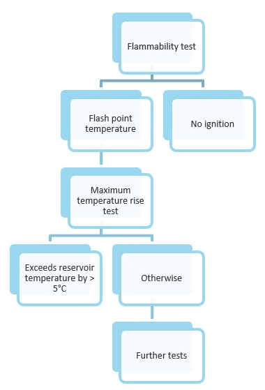
Figure 2 UL 9540A test sequence for flow batteries
RFBs are subjected to two main tests within the UL 9540A 4th edition test methodology: flammability of electrolytes and maximum temperature rise under abuse conditions as shown in Figure 2. Flammability of an electrolyte is determined by establishing its flash point temperature. Flash point temperature refers to the lowest temperature at which a chemical substance can vaporize to produce a combustible mixture at its surface. The flammability test method is dependent on the viscosity and the expected flash point temperature range of the electrolyte. The abuse conditions used to investigate the maximum temperature rise of electrolytes or reservoirs are mixing of fully charged (100% state of charge) positive and negative electrolytes, short-circuiting and overcharging the battery. The short-circuit and overcharge tests are conducted in accordance with UL 1973. The maximum temperature rise test is conducted only if the electrolyte is observed to have a flash point temperature during the flammability test. To characterize off-gassing in RFBs, the gases generated during flammability testing are captured and their compositions and flammability limits determined. The off-gassing volume of the test battery can be scaled for different sizes of similar RFB systems.5
A flow battery system is not subjected to any further tests if at least one of the following two conditions are met:
Electrolyte fails to ignite during flammability test
Flash point temperature exceeds the maximum reservoir temperature, observed under overcharge, short circuit and mixed electrolyte test conditions, by 5°C or more
UL 9540A also requires that the test report state an RFB’s compliance with UL 1973.5
The mixed electrolyte test is most similar to two failure modes in an RFB stack: membrane rapture and electrolyte failure. The VRFB reliability study has reported that the temperature of mixed electrolytes rises but the mixture does not ignite due to the aqueous nature of the electrolytes3 . The same study places electrolyte failure at low probability and low severity and membrane breakdown at low probability and high severity (see Figure 1). It is important to note that high severity in this case refers to the system’s loss of functionality, not fire risk3 .
Ultimately, the focus on electrolyte flammability as the sole source of risk in UL 9540A tests for RFBs is inadequate. A more comprehensive view of RFB fire risks could be achieved by characterizing the fire risks of the other RFB components which have demonstrated high combustibility and would present a safety hazard in case of external fires. RFB components such as the gaskets, membrane, bipolar plate, electrode frame and electrodes are composed of carbon and nitrogen compounds that release toxic COx and NOx gases during combustion. The investigation of the fire risks of a fully drained cell stack would also be valuable.
Perhaps the most significant guidance in UL 9540 are the energy capacity and separation distance limitations placed upon both residential (see Table 3) and non-residential BESS installations (see Table 4). Importantly, the safety advantages of RFBs are barely considered in setting the maximum aggregate energy capacity for FBES installations. The energy capacity limit of FBES equals that of lithium-ion BESS despite FBES’s inherent lower fire risks. Even though the energy capacity and distance limitations of UL 9540 are subject to large scale fire testing and AHJ approval, the energy capacity and separation distance cutoffs for FBES should exceed that of LIBs to reflect the inherent fire safety advantage of FBESs.
Table 3 UL 9540: Energy and separation limitations for residential installations6

Table 3 UL 9540: Energy and separation limitations for residential installations
Table 4 UL 9540: Energy and separation limitations for non-residential installations6

*Total aggregate energy capacity for LIB BESS and FBES only
The next article in this 3-article series delves into ways of addressing the gaps identified in this article.
References
[1] Invinity Energy Systems, Invinity Energy Systems, [Online]. Available: https://invinity.com/?utm_source=google&utm_campaign=20-04_branded_search&gclid=Cj0KCQjw852XBhC6ARIsAJsFPN08X7IzEBG7LtZGghxK-TwTF12snzo9cZAGhEKCb6Y8alCxCeY3IiYaAqm1EALw_wcB. [Accessed 5 August 2022].
[2] M. Paiss, ”Energy Response Solutions,” 11 August 2017. [Online]. Available: http://energyresponsesolutions.com/wp-content/uploads/VRB_SafetyReport.pdf. [Accessed 5 August 2022].
[3] F. Reichelt and K. Muller, “Assessment of the reliability of vanadium-redox flow batteries,” 2020.
[4] UL, “UL 1973, Standard for safety; Batteries for use in Stationary and Motive Auxiliary Power Applications,” 2022.
[5] National Standard of Canada, ANSI/CAN/UL 9540A Standard for safety: Test Method for Evaluating Thermal Runaway Fire Propagation in Battery Energy Storage Systems, Fourth Edition, 2019.
[6] UL, “ANSI/CAN/UL 9540: 2020; Standard for safety; Energy storage systems and equipment,” 2020.